Disconnect switch rotary disconnect switch visible blade disconnect switch enclosed disconnect switch control switch load switch allen bradley rockwell automation 1494u 1494v 1494c 194r hazardous location safety switch.
Allen bradley door mounted disconnect switch.
A full line of general duty heavy duty double throw and hazardous area devices is expanded with a series of innovative new products for a vast variety of applications.
Allen bradley disconnect switch family brochure subject.
Flange mounted disconnect switches are also available in an enclosure.
Flange mounted disconnect switches catalog number 1494f c233 fuse block adapter plate kit for fusible disconnect switch door hardware kit showing op side and bottom latching note.
2 a snap on fourth pole may be added on 16 125a switches.
Series r bulletin 2100 units page series d bulletin 2400 units publication 2100 6 0 2 september 1998.
1sxu000023c0202 english pdf catalogue 2013 product selector 19 disconnect switches complete section doc.
1 above 125a base mount with screws only.
Dimensions are not intended to be used for manufacturing purposes.
3 for a 6 or 8 pole switch 200 amp and above a conversion mechanism accessory kit can be used with two 3 or 4 pole switches.
Visible blade and rotary disconnect switches keywords.
Suitable as the main disconnecting means for a panel the 194u is available in front or base mounting styles together with side operation.
Tools and applications view all tools.
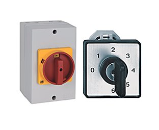
Non fused rotary disconnect switch 194u overview designed for global applications the allen bradley 194u non fused disconnect switch offers one of the smallest ul98 disconnects on the market.
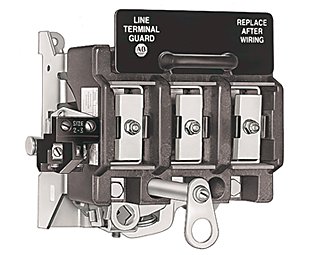
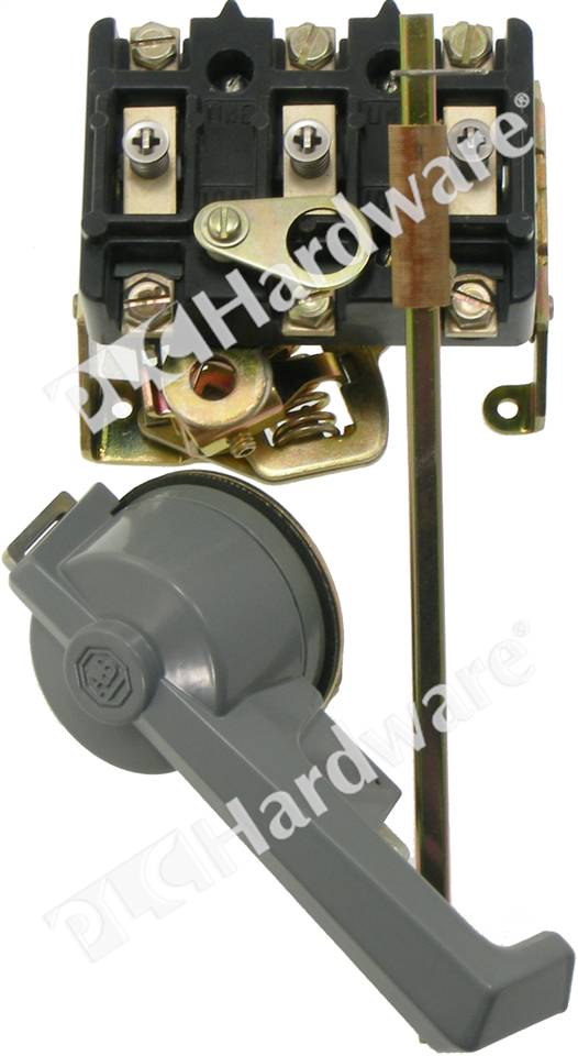
Our visible blade disconnect switches are available in both fixed and variable depth styles with flange or door mounting options.
Non fused rotary disconnect switch specifications approximate dimensions dimensions are in millimeters inches.
The left hand flange installation would have dimensions that are diametrically opposite.
Figure 1 30 60 and 100 a base mounted switches 3 pole devices figure 2 30 60 and 100 a door mounted switches 3 and 4 pole devices 100 3 93 100 3 93 8 8.
All drawings in this instruction sheet are for a right hand flange installation.


